CR10s Upgrades (2020)
My Customizations
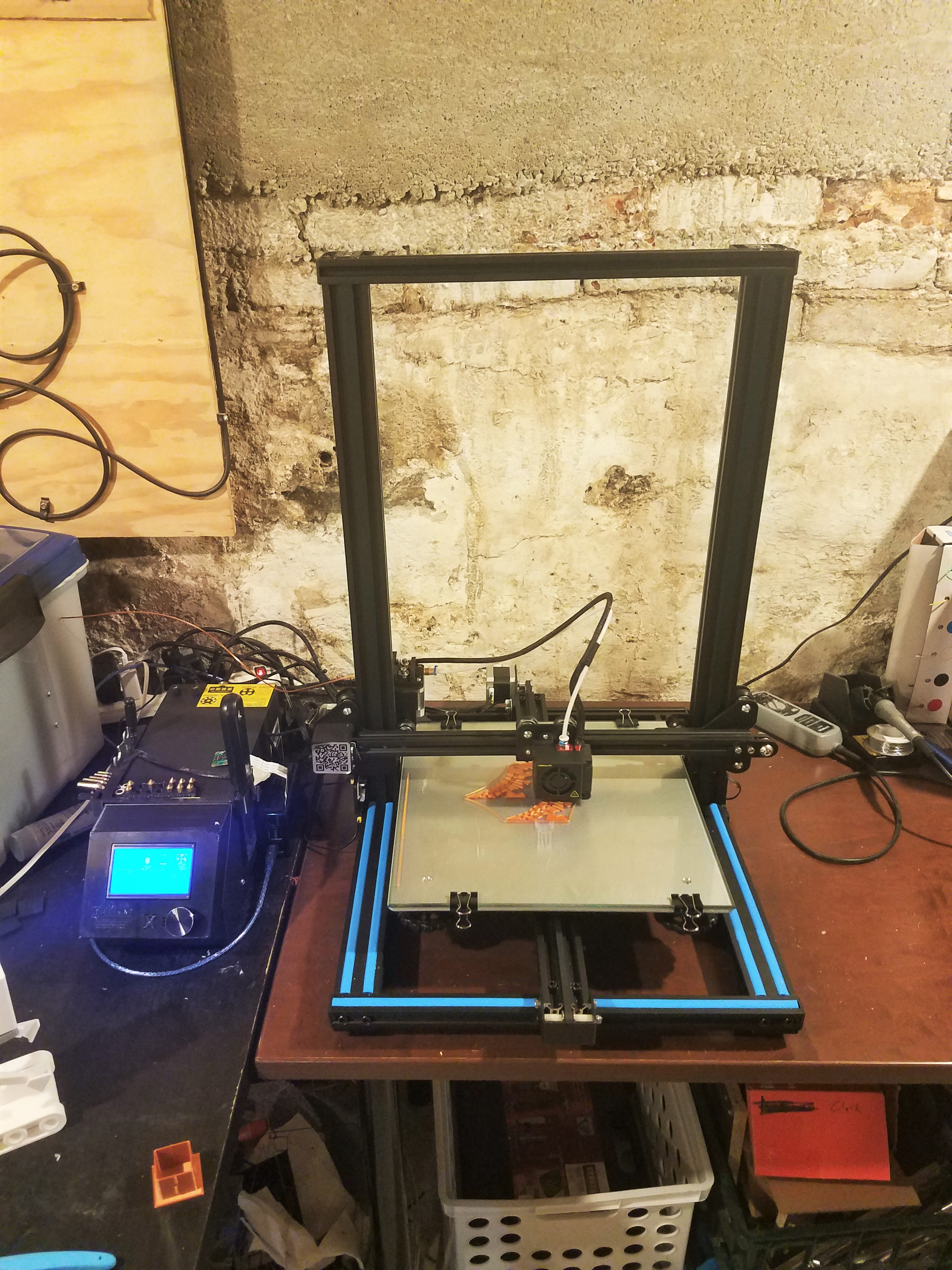
Base Model - CR-10s
Motor Drivers + Main Board
I was tired of how loud the CR10s is out of the box, so I figured I could quiet it down with some nice Trinamic motor drivers. However, Creality designed their own board for the CR10s with built-in motor drivers (pretty much the cheapest ones available). Luckily I had an extra RAMPS 1.4 main board with an Arduino Mega 2560 laying around to use.
The cheapo RAMPS 1.4 board has sockets for the motor drivers, so I chose the TMC2208 for its simple 1-wire UART connection and drop-in replacement into the board. However, replacing the board caused a ripple effect through the rest of the hardware:
- The stock Creality board uses JST connectors, while the RAMPS 1.4 uses classic pin headers. Thus, I had to crimp my own connectors onto wires for all the motors, switches, thermistors, and fans. Rather than actually modify the stock cables, I ordered a replacement cable set on Amazon for the switches and motors, and made some adapters for the thermistors and fans.
- The stock Creality LCD screen runs on 12V, but the Reprap Discount Full Graphic Screen that comes with the RAMPS 1.4 board runs on 5V. And guess what: The holes in the stock CR10s case don’t quite line up with the new screen.
Front Panel
Since the new LCD didn’t fit, I needed to make a new face plate. I decided to design one that snaps into place in the old cutout where the LCD use to sit. You can find the part on Thingiverse
Firmware
Enable UART with the TMC2208 Drivers
This is trickier than I thought it would be. It turns out the motor drivers i baught were wired differently from everyone else’s. After probably 3 days of troubleshooting and reading about 10 million blog posts, I finally found this YouTube video from the company I bought the drivers from (BigTreeTech). This clarified everything.
However, that wasn’t the end of thr road. It turns out Marlin 1.x doesn’t fully support TMC drivers. “It should be easy to switch up to Marlin 2.0 though,” I thought. Boy was I wrong. It turns out due to a complier problem in the Windows version of the Arduino IDE, I CAN’T COMPILE MARLIN 2.0 IN WINDOWS. Luckily I dual-boot my laptop, so a quick switch over to Ubuntu 18.04, and I was compiling Marlin 2.0 in no time. Literally 15 seconds.
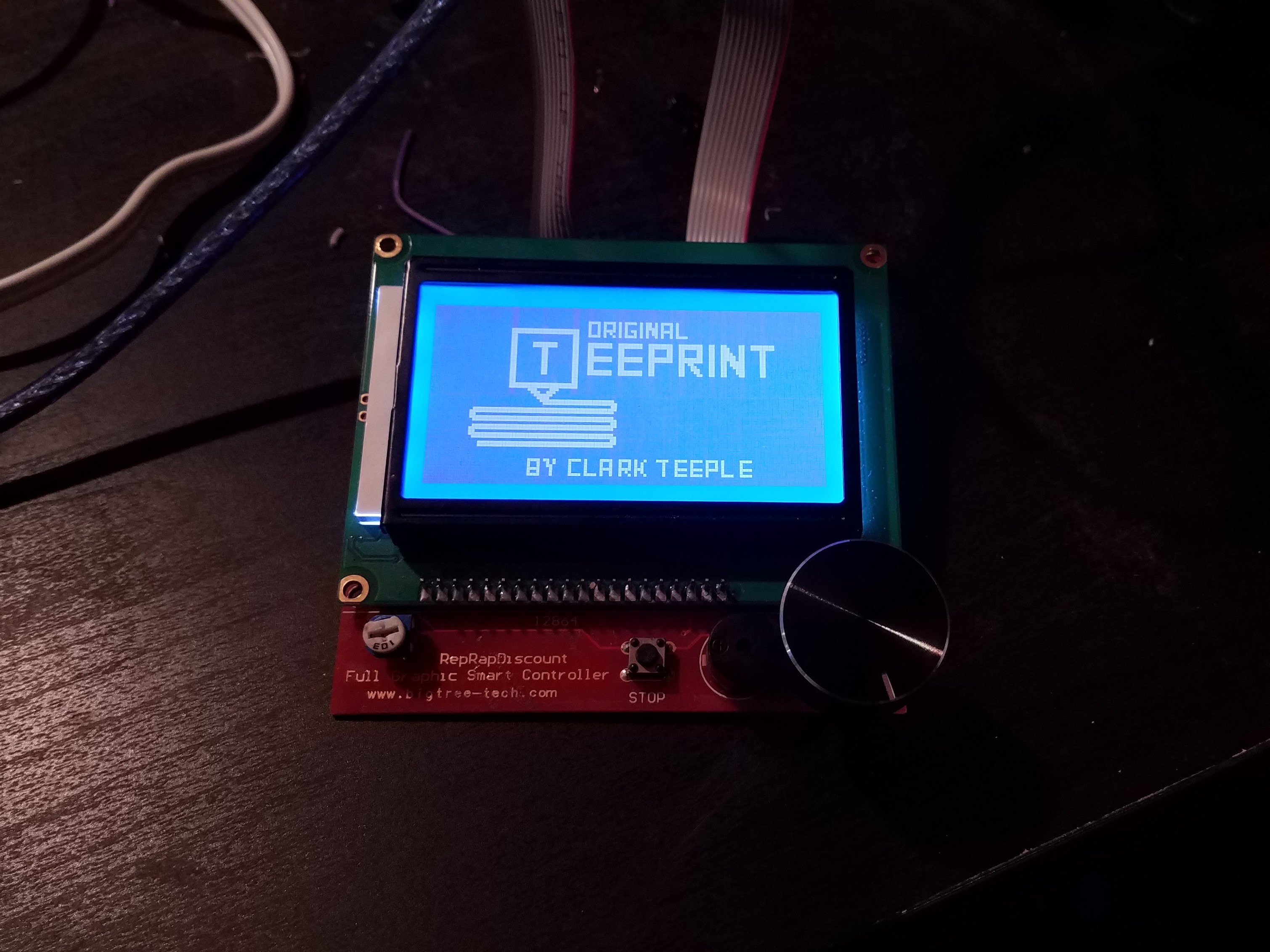
Boot Screen
After all of that nonsense getting Marlin to work, I figured I deserved a custom boot screen to commemorate all the hard work I’ve put into the printer so far. I followed these steps:
- Design the boot screen based on the instructions found on this blog post
- Use Marlin’s Bitmap to C/C++ Converter
- Select the “Boot” option
- Replace the
_bootscreen.hfile with this new one. - Hack the Marlin Firmware to only show this new boot screen
- By Default, Marlin will only has options to show Marlin’s default boot screen, show a custom screen in addition to the marlin screen, or show no boot screen.
- I obviously want to keep the boot sequence short, so I added another flag to the boot screen library that you can add in the configuration.h that disables the marlin boot screen.